Presented by SIGCS and The Department of Computer Science at Eastern Michigan University
This workshop is intended for teachers who are interested in learning to wire and program the Arduino. Arduinos will be supplied for use during the workshop. We are using kits purchased from Amazon and Parallax – Arduino robots.
Introduction:
I’ve been teaching a one semester class with Arduino for ten year. I learned how to use Arduino along with my students and my course has continuously evolved over time. My complete course is posted on this website.
From the Arduino website:
Arduino is an open-source electronics platform based on easy-to-use hardware and software. Arduino boards are able to read inputs – light on a sensor, a finger on a button, or a Twitter message – and turn it into an output – activating a motor, turning on an LED, publishing something online. You can tell your board what to do by sending a set of instructions to the microcontroller on the board. To do so you use the Arduino programming language (based on Wiring), and the Arduino Software (IDE), based on Processing.
Blink:
Lets make sure the boards will communicate and take a quick look over the Arduino IDE. We are going to cause an LED on the Arduino to flash at different rates.
Paste this Code into the Arduino IDE:
Here’s the complete code:
/* Blink Turns on an LED on for one second, then off for one second, repeatedly. This example code is in the public domain. */ // Pin 13 has an LED connected on most Arduino boards. // give it a name: int led = 13; // the setup routine runs once when you press reset: void setup() { // initialize the digital pin as an output. pinMode(led, OUTPUT); } // the loop routine runs over and over again forever: void loop() { digitalWrite(led, HIGH); // turn the LED on (HIGH is the voltage level) delay(1000); // wait for a second digitalWrite(led, LOW); // turn the LED off by making the voltage LOW delay(1000); // wait for a second } |
If you have programming experience this should look very familiar. If you are new to programming, this page will explain all the code. Play a bit, make the LED flash at different rates.
Now build the circuit shown below (need more help?). If you’ve done it correctly the LED on the Breadboard will flash along with the LED on the Arduino board.

Add on a couple more LEDs (don’t forget the resistors). Then make all the LEDs flash together and/or in sequence.
Digital Input:
Next we’ll add in a push button. Build this circuit:

Try this Code. You won’t see anything unless you open the Serial Monitor:
int buttonPin = 2;
int buttonState = 0;
int led = 10;

void setup() {
  pinMode(buttonPin, INPUT);
  pinMode(led, OUTPUT);
  Serial.begin(9600);
}

void loop() {
  delay(10);
  buttonState = digitalRead(buttonPin);

  if (buttonState == HIGH)
  {
    digitalWrite(led, HIGH);
    Serial.println("Button Pressed");
  }
  else
  {
    digitalWrite(led, LOW);
    Serial.println("Button Released");
  }
}
Now, do something with the second LED. Doesn’t really matter what. You should also check out the Serial Monitor. You should notice that “Button Pressed” and “Button Released” print over and over again. This code will stop that from happening:
int buttonPin = 2;
int buttonState = 0;
int buttonPressed = 0;

void setup() {
  Serial.begin(9600);
  pinMode(buttonPin, INPUT);
}

void loop() {
  delay(100);
  buttonState = digitalRead(buttonPin);

  if (buttonState == HIGH && buttonPressed == 0)
  {
    Serial.println("Button Pressed");
    buttonPressed = 1;
  }

  if (buttonState == LOW && buttonPressed == 1)
  {
    Serial.println("Button Released");
    buttonPressed = 0;
  }
}
This should print Button Pressed only one time when the button is pressed. This idea can be built upon to create a toggle. The code below will turn an LED on when the button is pressed and the LED will stay on until the button is pressed again.
HIGH, true, and 1 are Synonymous:
int buttonPin = 2;
int buttonState = 0;
int buttonPressed = 0;
int ledPin = 10;
bool ledState = false;

void setup() {
  Serial.begin(9600);
  pinMode(buttonPin, INPUT);
  pinMode(ledPin, OUTPUT);
}

void loop() {
  delay(100);
  buttonState = digitalRead(buttonPin);

  if (buttonState && !buttonPressed)
  {
    Serial.println("Button Pressed");
    buttonPressed = 1;
    ledState = !ledState;
  }

  if (!buttonState && buttonPressed)
  {
    Serial.println("Button Released");
    buttonPressed = 0;
  }

  digitalWrite(ledPin, ledState);
}
Analog Read and Write:
Time to explore the Example Sketches. In the Arduino IDE open:
File->Examples->Analog->Fading
Wire an LED (with resistor) up to Pin 9 and upload the code. You should see your LED pulsing on and off. Can you make it faster? Slower?
Things to know:
-
- analogWrite is 8 bit (0-255)
- overflow – 256 is the same as 0
- Only certain pins support analogWrite. Marked with either PWM or a ~
Next load up:
File->Examples->Analog->AnalogInput

Change the cod to light up the LED plugged into pin 10. The turn the knob to see the flash rate change. Then try this code:
int sensorPin = A0;
int ledPin = 10;
int sensorValue = 0;
int val = 0;

void setup() {
  pinMode(ledPin, OUTPUT);

}

void loop() {
  sensorValue = analogRead(sensorPin);
  val = map(sensorValue, 0, 1023, 0, 255);
  analogWrite(ledPin, val);
}
analogRead returns a 10 bit number (0 – 1023), so we use the map() function to adjust it to use with analogWrite. If you are feeling ambitious you can swap your potentiometer out for a light sensitive resistor (Note: the code example on this page is incomplete. You will need to fix it).
Make things Move
Next dig out the Servo motor and wire it as shown below:

Open: File->Examples->Servo->Knob
Note: Standard servo motors adjust from 0 to 180°. Here we use map() to adjust our analogRead values to this range.
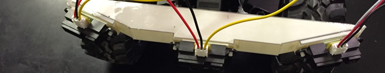
Arduino Robot
We are using the NICERC Shield Bot with Arduino Kit. The kit comes with a complete guide, but I don’t know that I’d use it as more than a general reference. I should note that I am not a classically trained coder. So I might be wrong in this.
Here are a couple of my general recommendations:
- Do not use Pins 12 and 13 for the servos as recommended. When an Arduino is powered up or reset it hits pin 13 briefly. If you use Pin 13 for one of your servos the robot will move slightly when this happens. Instead use the other set of headers, which are wired to pins 10 & 11.
- You might want to use servo.write() instead of servo.writeMicroseconds(). Most of the example Arduino servo code you (or your students) will find on the net uses servo.write(). Additionally if you add a standard servo to the robot later you will probably use this function as well.
I will be using servo.write() in this workshop. The servo motors on our robots have been modified to be continuous rotation servos. Wire your potentiometer (from the Arduino Kit) to your robot as shown:

Use the Servo example sketch we used earlier: File->Examples->Servo->Knob
Change the servo pin to one of the pins attached to our robot’s servos. Note how the wheel responds as you adjust the servo. For continuous rotation servos, 90° should cause the servo to stop, 0° is maximum speed in one direction and 180° is max speed in the other direction.
Be sure the robot’s servo motors are attached to pins 10 & 11 (or change the code) and try this:
#include <Servo.h>

Servo left;  // Creates an instance of Servo for the left motor
Servo right; // Creates an instance of Servo for the left motor

void setup() {
  right.attach(10); // attach right servo to pin 10
  left.attach(11);  // attach left servo to pin 11

  forward(1000);
  turnRight(900);
  forward(1000);
  turnLeft(900);
  stop();
}

void loop() {

}

void stop(){
  right.write(90);  // setting servos to 90 degrees
  left.write(90);   // stops them from turning
}

void forward(int driveTime){
  // Both just as far from 90 degrees means both motors
  // should be turning the same speed. Opposite directions
  // becuase motors are oriented in different directions.
  right.write(60);
  left.write(120);
  delay(driveTime);
}

void backwards(int driveTime){
  right.write(120);
  left.write(60);
  delay(driveTime);
}

void turnRight(int turnTime){
  right.write(90);
  left.write(120);
  delay(turnTime);
}

void turnLeft(int turnTime){
  right.write(60);
  left.write(90);
  delay(turnTime);
}

void disableServos(){
  right.detach(); // disconnect servos
  left.detach();
}
Challenge: Write code to navigate the course taped out on the floor.
Add simple sensors to your robot:
Flip to page 148 in the guide and add the Whiskers to your robot.

The Whiskers act as push buttons. In their current configuration they will read as HIGH when the whisker is not touching anything. When the whisker is pushed back into the headers, this will “close” the button and the digitalRead() will return LOW.
Here’s some quick code I put together to read the whiskers:
#include <Servo.h>

Servo left;  // Creates an instance of Servo for the left motor
Servo right; // Creates an instance of Servo for the left motor

bool rightWhisker;
bool leftWhisker;

void setup() {
  pinMode(7, INPUT);
  pinMode(5, INPUT);


  right.attach(10);
  left.attach(11);

}

void loop() {

  forward(10);

  rightWhisker = digitalRead(7);
  leftWhisker = digitalRead(5);

  if(rightWhisker == LOW){
    backwards(500);
    turnLeft(900);
  }else if(leftWhisker == LOW){
    backwards(500);
    turnRight(900);
  }
}

void halt(){
  right.write(90);  // setting servos to 90 degrees
  left.write(90);   // stops them from turning
}

void forward(int driveTime){
  right.write(60);
  left.write(120);
  delay(driveTime);
}

void backwards(int driveTime){
  right.write(120);
  left.write(60);
  delay(driveTime);
}

void turnRight(int turnTime){
  right.write(90);
  left.write(120);
  delay(turnTime);
}

void turnLeft(int turnTime){
  right.write(60);
  left.write(90);
  delay(turnTime);
}
It could probably use some additional tweaking and maybe an extra function or two to make it work better. This one will get stuck in a corner pretty easily. Can you change the code to keep that from happening?
Where Steve Buys stuff:
- Arduinos, Shields, other cool stuff: SparkFun and Adafruit (both are also great places to learn stuff as well)
- General Electronics Components: Electronic Goldmine, Electronic Express, and Amazon


You must be logged in to post a comment.